


FRICTION WELDING
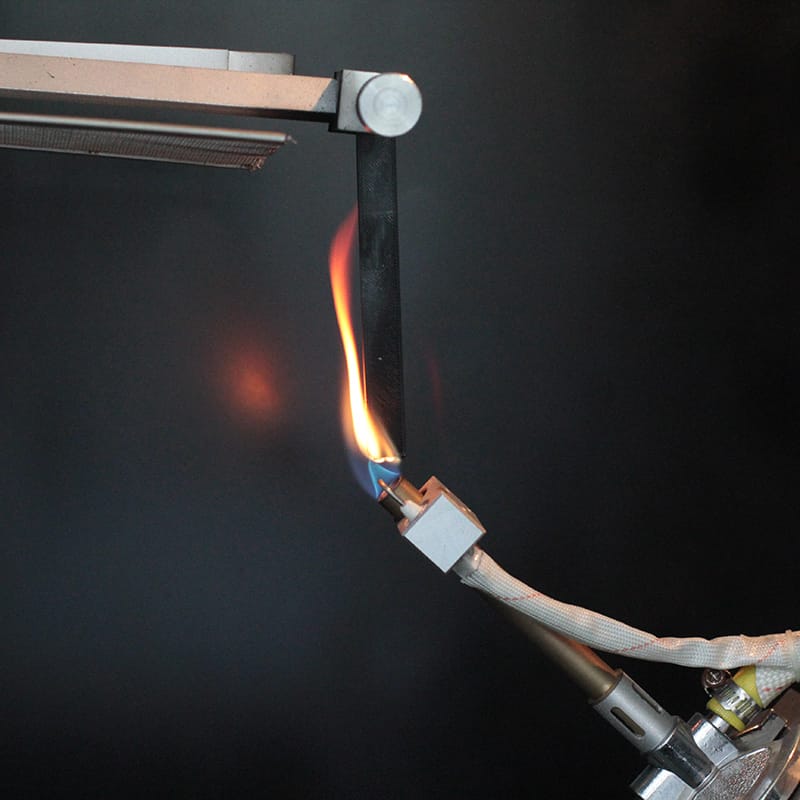
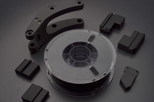
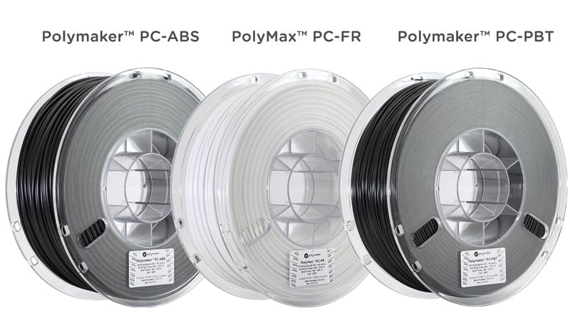
In the early days of 3D printing when the first printers were being developed, the only material the inventors could get their hands on was ABS. This was largely due to the availability of ABS welding rods which were already being produced at the time and happened to a convenient shape and diameter. So it seems this historic relationship between 3D printing and plastic welding is deeply routed in the extrusion based technology. In this article and tutorial I’d like to show you how to harness this technique and explore its full potential. What makes this process so easy nowadays is the availability of welding rod, which in this case is the filament you used to print your models. At its heart, friction welding is the process of welding two objects together by harnessing the heat generated by friction. To generate the heat required to melt the plastic you’ll need a rotary tool. The collar on my rotary tool better suits a 2.85mm – 3mm filament and in the video I’m using PolyMax as that was the same material I used to print my objects. Once the filament is spinning in the rotary tool the idea is to gently feed the fast spinning filament into your seem line. The friction created from the rotation raises the filament and model to their glass transition temperature at which point you feed the filament into the seem. There are a few different techniques to apply when welding, each with their own benefits.
Pulling Technique
In this technique you want to position the rotary tool so the filament is pulling along the seem line. This way the edge of the filament has time to cut a channel into the two sides.Angle the rotary tool to around 45°. During the cutting process the friction raises the temperature of the filament and it subsequently melts into the channel. This is a very good welding technique as the molten plastic penetrates down through the layers and after a bit of practice with pressure and speed you can get the plastic filling the channel nicely. Take note of the direction of your rotary tool. My rotary tool spins clockwise, this means that the rapidly cooling plastic is always being dragged in a clockwise motion and you tend to get a larger build up of material on the right hand side of the weld. So you may need to do another pass on the left hand side to make a truely seem less weld.
Small Circles Technique
This technique is borrowed straight from MIG welding. This is the technique I was taught when welding steel, the trick is to drag the molten plastic over the seem line stitching the two parts together. When done properly its a great one time welding technique and if you use contrasting colours to weld with you should be able to see the different hues blending in the weld. The angle of the rotary tool wants to be raised to around 70° – 80° this means that more heat is focused in the tip of the filament and as it passes over the seem line it stitches the two parts together. Generally the weld also sits proud of the surface which is ideal if you want to grind and sand back your weld to a flat surface. The downside to this technique is that it doesn’t cut a deep channel into the printed parts. This means you end up with a surface weld which isn’t as strong as the pull weld. If your looking purely for aesthetics then this is a great looking weld as the concentric circles mimic that of a metal weld. Try combining the two techniques for a strong and seem less weld.
Right to Left Technique
Also a great technique for the one hit weld. If your rotary tool spins anti clockwise then this technique becomes left to right instead. The advantage over the pull weld is the the excess material that was building up on the right hand side of the weld is now sitting on top of the seem. This technique also cuts a channel, making it stronger than the small circles weld. However the penetration depth doesn’t match that of the pulling technique. You can adjust the rotary tool to a shallow angle when using this technique and the shallower you go the deeper your channel will become.
Gap and Hole Filling
If you have already bonded your parts together and are happy with the strength of the joint. You can use a plastic with a lower printing temperature (therefore lower melting temperature) to fill small gaps and holes. By using a filament with a lower melting temperature you can ensure you build enough heat into the filament without making the gap or hole any larger. Its best to angle the rotary tool to 90° to the part, this way the smallest surface area of plastic is heating up ensuring that it melts quickest. Combine the small circles technique with a lower melting filament for best results.